A Great Tool for Fluorescence Quenching Studies and Stern-Volmer Analysis – the Story Behind our Automated Continuous-flow Platform

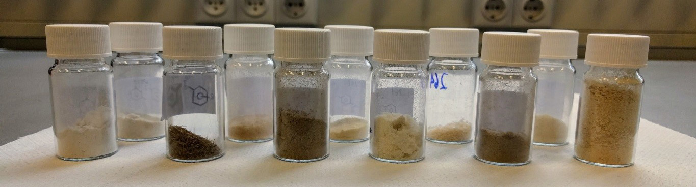
Frustration as a source of inspiration

I am pretty sure any PI can name a few experiments which their students detest. Not because they are useless (despite the often-used bluff feedback that it is “not absolutely necessary” for the paper), but because these experiments are tedious, time-consuming and frustrating. Amongst the most hated experiments, one could easily place measuring IR spectra (Such an old technique, who needs that anyway?), distilling reagents and solvents (Can’t we just buy a new bottle?), titrations (Do you not believe the concentration written on the bottle?), … In our lab, and probably in many other ones, a special place on that ranking is occupied by Stern-Volmer analysis.

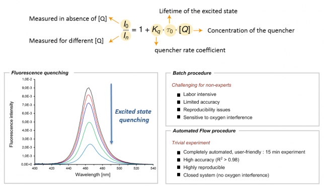
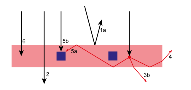
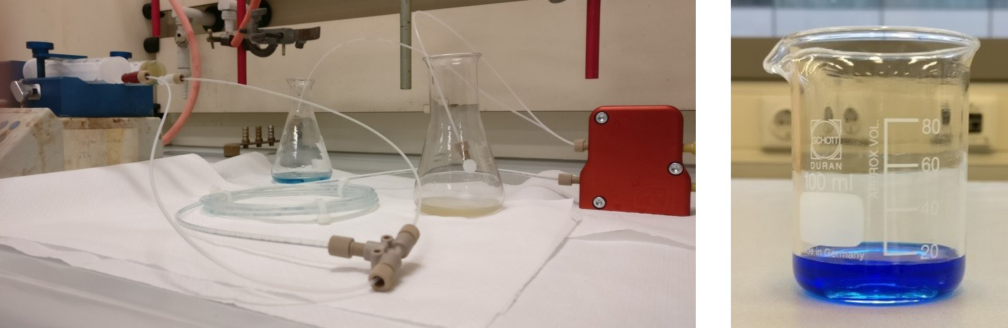
Those of you working on photoredox catalysis probably know too well what I am talking about. For those who don’t, here’s a brief explanation: once in their excited state, photocatalysts tend to return to their ground state by dissipating the energy in the form of emitted light (also called fluorescence). However, in the presence of appropriate organic molecules (often referred to as quenchers), the excited photocatalyst can transfer that excited state energy to a suitable quencher via a single electron or energy transfer. As a result of this interaction, a reduction in the fluorescence of the photocatalyst can be observed (Figure 1). The kinetics of this phenomenon can be explained by the Stern-Volmer relationship, thus making this experiment crucial to elucidate which molecule(s) can interact with the photocatalyst and at which rate they can do so. In other words, the Stern-Volmer relationship provides valuable information in the elucidation of any photocatalytic reaction mechanism.

However, as for all kinetic studies, Stern-Volmer kinetics is not that easy (Figure 1). The process is labor-intensive and sensitive to oxygen, thus often making it difficult to obtain quantitative data. In our own experience, we noticed that, depending on the students’ experience (BSc, MSc, Ph.D. or postdoc level), we usually obtained good qualitative results but the reproducibility and accuracy of the data were often problematic. Since we strive to publish the best achievable data, this eventually resulted in the necessity to repeat the experiment several times, sometimes even by several different students. Talking with other colleagues in the field, we realized this was somewhat a general issue in many groups. In some labs, they even attempted to fix this problem by appointing one student as the Stern-Volmer expert, in order to avoid wasting too much time.

As frustration is typically a good reason to initiate change, we felt that an automated tool to conduct Stern-Vomer analysis would be extremely useful (Figure 1). It would not only greatly reduce valuable experimental time but it would also make sure that the process can be carried out with high precision and reproducibility by basically any chemist, regardless of their experience. Automated platforms have become increasingly important and have often been combined with flow chemistry to assist chemists in their synthetic efforts. Seminal works by the groups of Jensen (MIT), Bourne (Leeds), Ley (Cambridge), Rueping (RWTH) and many others have paved the path for a future in which a machine-assisted approach towards organic synthesis allows chemists to disregard the routine aspects of their laboratory work.[1] Indeed, we felt that Stern-Volmer and other quenching studies were requiring too much of our precious research time.

Figure 1. Stern Volmer kinetics: the equation (top), fluorescence quenching by adding increasing amounts of quencher (bottom left), comparison batch and automated flow procedure (bottom right).

The kick-off of our automation activities

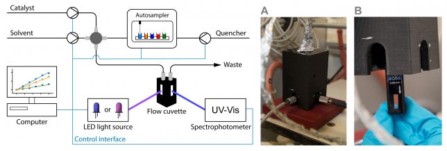
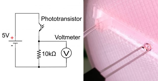
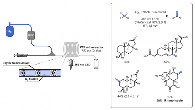
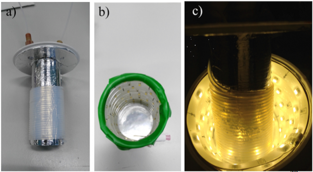
At that point, we had little to no experience with the automation of chemical processes. However, at TU Eindhoven, we are lucky to have every year bright Chemical Engineering MSc students, who are motivated to take on important challenges within their graduation thesis. Under Koen Kuijpers and Dario Cambie’s supervision, Koen Drummen (having too many Koens at the same time in the lab was also confusing for us, so we started calling them Koen2 for brevity J) started his thesis in September 2016 working on the project. He took our UV-VIS spectrophotometer (Avaspec-2048) and equipped it with a 100 μl quartz flow cuvette which allows measuring the fluorescence of the photocatalyst (Figure 2). Inspired by the Glorius mechanism-based luminescence screening method,[2] we also envisioned to carry out automated screening experiments of various quenchers. For this reason, Koen Drummen also installed an autosampler which allowed us to inject different quenchers sequentially into the continuous-flow stream.

Figure 2. Schematic representation of the automated platform. 3D-printed customized holder for the flow cuvette (inlet right and outlet left). Close-up of the flow cuvette housed within the holder.

Installing and connecting all the different units together was relatively straightforward. The real confrontation, in this case, was to write a suitable code to make sure all the different units can talk to each other. Hereto, we had to learn Python. I still remember entering the office and seeing Koen2 watching YouTube videos to solve all their issues with the code. Who doesn’t love a nice YouTube tutorial? We partly have to thank some YouTubers: in the end, Koen2 fixed the code and started to run the first automated fluorescence quenching screenings.

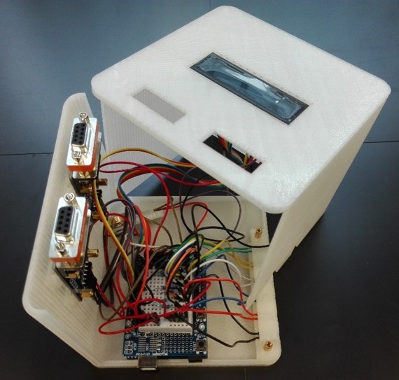
Next, we also developed a graphical user interface which allows you to rapidly fill in the compounds to be screened (Figure 3). This makes the entire automated setup really intuitive, basically making it possible for anyone to perform Stern-Volmer quenching experiments, regardless of their ability to code. A cool feature of our software is that, once the analysis is finished, the results are automatically sent by email as a pdf file. Easy enough, right?

Figure 3. Screenshots of some of the graphical user interfaces of the software developed for the automated platform.

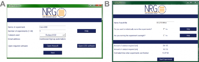
At that point (we are now early 2017), another MSc student, Niels Koenig, joined our group eager to further improve the software. He added a new feature to the software, namely the possibility to automatically color-code the results obtained in the quenching experiments. If a compound was found to be a strong quencher (> 50% quenching efficiency), a green color was assigned to its fluorescence peak while a weak quencher (< 25% efficiency) was assigned a red color. This feature gives in one blink of an eye the confirmation on which quenchers are interesting to test in further reactions and which ones can be discarded.

Time to test the automated platform.

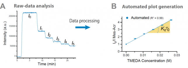
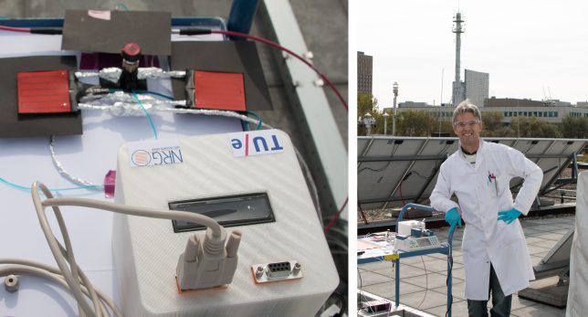
Once our engineers had a working platform ready, it was time to put it to the test. At this point, I asked our photocatalysis expert Cecilia Bottecchia to collaborate with Koen Kuijpers to see how we could take advantage of the technology. The first thing we did was a Stern-Volmer analysis to determine the rate at which TMEDA can quench the excited state of 9-mesityl-10-methyl acridinium perchlorate (Mes-Acr+) (Figure 4). By adding in flow increasing concentrations of quencher, a progressive decrease of the fluorescence emission intensity can be observed. Next, the software converts the obtained data into the classical linear Stern-Volmer profile. From the slope of the line, one can now easily obtain the quenching kinetic constant for a certain quencher. Notably, ten consecutive experiments demonstrated that the data produced by our automated platform was consistent and reproducible, with exactly the same slope (and thus quenching kinetic constant) in each experiment! What a difference compared to our laborious manual procedure!

With the optimized system, we could now run a single Stern-Volmer experiment within only 15 minutes. The only thing you need to do is to prepare the photocatalyst and the quencher solutions. After that, it’s all about hitting the start button, sit back, relax (or work on something else :)) and enjoy your results.

Figure 4. Quenching of Mes-Acr with increasing amounts of TMEDA: (A) Raw data obtained by the automated platform; (B) Stern-Volmer plot automatically generated by the software. Note the tiny error bars, which reflects the data of 10 consecutive experiments.

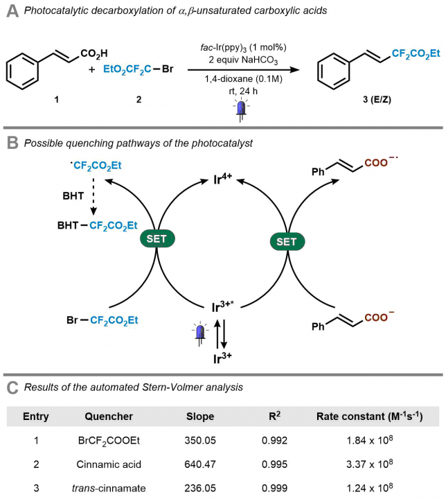
Next, we investigated several case studies to validate the screening option of our platform. One specific example that we carried out was the mechanistic investigation of the Ir(ppy)3-catalyzed photocatalytic decarboxylation of cinnamic acids developed by Xiao-Jing Wei in our group.[3] Cecilia prepared the stock solutions and found rapidly that the software and hardware could rapidly generate the data which was required to elucidate the mechanism (Figure 5). It should be noted that in all cases, we obtained high-quality data with R2 >0.99. Now, in one single hour, we obtained both qualitative and quantitative data, while previously we had to struggle sometimes days to get the quantitative data. It might still be true that, as one referee pointed out, “a good photochemist can run a Stern-Volmer analysis in 30 minutes” but we still believe that you will have to work really hard to get everything done in this timeframe. We did some other screening procedures with our system as well but we invite you to have a look at our paper for all the experiments we did. The bottom-line is that such experiments have become a piece of cake making it actually fun to do.

Figure 5. Results obtained with our automated platform for the mechanistic investigation of the photocatalytic decarboxylation of cinnamic acids to access difluoromethylated styrenes.

Outlook

Automating luminescence quenching studies has been one of those projects that really changed the daily life in our group. Before we had access to this platform, students hated me when I asked them to do this experiment. One even said (not a joke): “I’d rather add ten more substrates to the scope instead of doing the Stern-Volmer studies!”. While I could not be bribed (I asked for both the substrates and the SV analysis :)), I still felt that it was crucial to at least alleviate the unnecessary issues that these experiments bring along. We also like the story behind this project because it clearly shows how certain ideas take shape within our group: we wanted to develop some novel synthetic methods via visible light photoredox catalysis, but we ended up with a creative solution to overcome technical hurdles along the way. Simply put, we found a mean to our end. One anonymous referee during the peer-review process really made us proud:  “This article presents a valuable and practical advancement for the field of photoredox catalysis. […] Overall, the development of an automated flow platform that significantly accelerates the collection and processing of fluorescence quenching data in a time and labor-efficient manner will be immediately impactful to the organic community.” Our system was and still is impactful in our group and we all hope it will be for your work as well! Don’t hesitate to contact us if you want to give it a shot!

Figure 6. The two first-authors of the paper: Koen Kuijpers and Cecilia Bottecchia or also Chemical Engineering meets Chemistry. A diverse duo to solve this interdisciplinary challenge.

See you,

Tim, Cecilia and Koen

The paper discussed in this blog was published as: A fully automated continuous-flow platform for fluorescence quenching studies and Stern-Volmer analysis. K. P. L. Kuijpers, C. Bottecchia, D. Cambie, K. Drummen, N. Koenig, T. Noël, Angew. Chem. Int. Ed. DOI: 10.1002/anie.201805632.

References:

[1] (a) D. E. Fitzpatrick, C. Battilocchio, S. V. Ley, Enabling Technologies for the Future of Chemical Synthesis. ACS Cent. Sci. 2016, 2, 131-138. (b) B. J. Reizman, K. F. Jensen, Feedback in Flow for Accelerated Reaction Development. Acc. Chem. Res. 2016, 49, 1786-1796.

[2] M. N. Hopkinson, A. Gomez-Suarez, M. Tederes B. Sahoo, F. Glorius, Accelerated Discovery in Photocatalysis using a Mechanism‐Based Screening Method. Angew. Chem. Int. Ed. 2016, 55, 4361-4366.

[3] X.-J. Wei, W. Boon, V. Hessel, T. Noel, Photocatalytic Decarboxylation of α,β-Unsaturated Carboxylic Acids: Facile access to Stereoselective Difluoromethylated Styrenes in Batch and Flow. ACS Catalysis 2017, 7, 7136–7140.

How to Have Complete Control over Your Solar Photochemistry During Cloudy Days – Insight in our Real-time Reaction Control System

Our latest paper on a real-time reaction control system for the solar production of chemicals under fluctuating irradiance was published online today in Green Chemistry (DOI: 10.1039/c8gc00613j). Our solar-photochemistry research has always been characterized by the desire to reduce the gap between the lab and the rooftop, in other words we want to enable the use of sunlight as a free light source for many photochemical reactions in a simple and efficient way. With the Luminescent Solar Concentrator PhotoMicroreactor (LSC-PM) design we introduced a novel way to convert the polychromatic solar spectrum into a narrow band, while now we addressed the issue of light intensity fluctuations (e.g. due to passing clouds).1 Here, we will give you some inside information on our solution for this important issue within solar photochemistry.

Figure 1 Graphical Abstract of our “Real-time reaction control for the solar production of chemicals under fluctuating irradiance”

The problem with sunlight variable intensity
To the chemist inclined to perform photochemical reactions with solar light, one of the main limitations is represented by the uncontrollable fluctuations in solar irradiance. In particular, while the daily and seasonal variation can be predicted, short fluctuations introduced by passing clouds are the most difficult to address. In the past, we experienced this first-hand when we tested outdoors our reactions (e.g. see Figure2).

Figure 2 Impact of sky conditions on solar reaction performance.

The idea

To use the words of an anonymous reviewer, “It is common knowledge that the kinetics of photoreactions are often governed by the supplied photon flux.” Using a light sensor for adjusting the irradiation time to compensate the different irradiance might, therefore, seem trivial. Alas, reality is unfortunately far from that!

For example, the spectral distribution of solar light can change significantly throughout the day. Other than the obvious red color of sunlight at sunset and sunrise, also cloud coverage, atmospheric humidity, ground albedo and other parameters can affect the wavelength distribution of solar radiation at the ground. The only reason why we could keep our system simple is that we used a Luminescent Solar Concentrator PhotoMicroreactor (LSC-PM). In an LSC-PM, the incoming solar radiation is absorbed by a fluorescent dye that re-emits the absorbed photons in a polymeric lightguide as a down converted and narrowband beam corresponding to the dye fluorescence spectrum (see Figure 3). As a consequence of the adoption of the LSC-PM design, we could neglect the variation in sunlight spectral distribution! Furthermore, by placing a light sensor in direct contact with the device edge, the light intensity measured is proportional to the photon-flux experienced by the reaction mixture flowing in the reactor channels.2

Figure 3 LSC-PM working principle. The solar photons reaching the device are either reflected (1), transmitted (2)  or absorbed within the device. Most of the photons are absorbed by the dispersed dye molecules (red dot) that re-emit fluorescent photons that are waveguided to the reaction channels (5a) or to the device edge (4).Eventually, our reaction control system is simple and elegant. As in the quote often attributed to Leonardo da Vinci, we could say that simplicity, in this case, “is the ultimate sophistication”. 🙂

Merging chemistry and electronics

Being aware of the relationship between the light intensity emitted at the device edge and the photon flux in the reaction channel, we had to find a way to measure the former as an estimation for the latter. Thanks to the advancements in electronics, that is not a difficult task. After all, most of our smartphones have a little sensor to adjust the screen backlight to the ambient light conditions.

After a brief screening of different light sensors (photoresistors, phototransistor, integrated circuits based on PV cells) we decided to use a phototransistor thanks to its simplicity. By including it in a voltage divider circuit, the variation in the light intensity can be measured as a variation in the voltage drop across a resistor connected in series (see circuit in Figure 4).

Figure 4 Schematics of the light sensing circuit used (left) and a photo of the phototransistor fixed in a 3D printed holder to keep it on the device edge (right).

Kinetic data

With a working sensor in our hands, we needed to perform the calibration between the different light intensity levels, and the corresponding conversion at different residence time. This can be a rather laborious work but, as you might have noticed at this point, in our group we are not afraid of merging chemistry and technology. Therefore, we have developed a simple python script to control pump flow rate and LED light intensity (with a MOSFET) while measuring the reaction conversion was measured in line with a UV-VIS spectrometer. As such, this data can be obtained in fast, automated and reliable fashion.

Timing is everything

After gathering all the required data, finding the voltage/residence time relationship to keep the conversion stable was relatively easy. The first tests of the system with an artificial set of light variation were both encouraging and alarming. While the system was actually capable of adjusting the residence time to match the variation of light intensity, its reactiveness was too slow.

For a moment we feared that this might be an intrinsic limitation of our reactor (e.g. due to its elastic nature or modest volume). It turned out that the major source of variability was the delay between the light intensity reading and the adjustment of the pump flow rate. While the phototransistor responsiveness to light variation was almost instantaneous3, most of the delay was in the computer controlling the pump and the pump actually changing the flow rate. By reducing the loop time in the reaction control script to the pump response time, an update rate of less than a second was achieved. After this correction, a good stability in the reaction conversion was obtained even for large and fast variation to the external irradiance.

Arduino

Up to this point, we had been using a PC to interface with a voltmeter to read the voltage drop and to change the pump flow rate accordingly. The system was fine for lab development, but clearly, we could not propose to use it as such to control multiple reactors in a hypothetic solar mini-plant. The advantages of switching from a reaction analysis approach to monitor the reaction progress to a physical measurement that directly addresses the source of variability and that can predict the reaction outcome represented a significant conceptual difference.

We went back to the drawing board and decided to simplify the overall system with the adoption of an Arduino microcontroller. Once programmed with the kinetic investigation data, the controller would automatically send commands to the syringe pump to correct the flow rate based on the voltage measured in the light sensor. In this way, both the multimeter and the PC are replaced by an inexpensive integrated circuit. Tim particularly liked the inexpensive nature of this solution, whose total cost was about 50€. Actually, by using a generic Arduino instead of a genuine one or by including all the components in a single printed circuit board, the price of the system could be decreased to less than 10€ per piece (and even further in case of mass production).  We believe that this system has potential to be applied for the reaction control of every solar photoreactor tested outdoors. To describe it with the words of another anonymous reviewer: “The potential of this to thus be completely automated will bring legitimacy to the idea of actually using solar to perform synthetic organic chemistry in practice”. And that is exactly the goal we are working towards!

Figure 5 The 3D-printed box with the Arduino microcontroller that we used for the experiments. It is possible to connect up to 6 phototransistors (bottom right) and two between pumps and mass flow controller (serial connections, on top). The measured voltage and status are shown in the display on top.

Outdoor experiment

Finally, as usual in our LSC-PM papers, we tested the reaction control system outdoors on a cloudy day, luckily those cloudy days are quite common here in Eindhoven… The system worked as planned and could handle challenging weather conditions (read: frequent and steep variations due to passing clouds). Once we got these results, we went back to the office with a big smile and finalized the paper writing process.

Figure 6 On the left the setup used for the outdoor experiments, the reactor on the left is connected to the light sensor while that on the right is not. On the right, our PI Tim, checking that everything runs smoothly during our experiments on the rooftop of the Architecture Department building.

Outlook

It is undeniable that the dilute nature of solar energy will never make it suitable for the production of bulk chemicals. The volumes and margins of fine and specialty chemicals, on the other hand, constitute a real possibility for solar photochemistry. One should also realize that the use of solar energy is basically for free and abundantly available. Especially when energy prices will rise (it is just a matter of time), these technological solutions might make the difference! We believe that our paper is yet another step in our lab’s effort towards simple and more efficient solar photoreactors. Ultimately, we hope to see our technology implemented in the solar synthesis of some life-saving drugs! 🙂 🙂

Bye!

Fang, Dario, and Tim

1 To this is particularly relevant the Whitesides’ recent perspective on the future of organic chemistry: “Another possible direction for the future evolution of Organic Synthesis is, in effect, to fuse (at least in part) with Chemical Engineering, and use the techniques of that area to simplify processes […]

2 More details on this in the Monte Carlo ray-tracing simulations that we have published last year.

3 10 µs according to manufacturer specifics

Decatungstate-mediated sp3 C–H Aerobic Oxidation in Continuous Flow

We are delighted to announce that our latest publication on the decatungstate photocatalytic sp3 C–H aerobic oxidation in flow is now available on the website of Angewandte Chemie (DOI: 10.1002/anie.201800818 ). Here, we would like to share the “logbook” of this scientific journey. Fasten your seatbelts and let’s go!

TBADT-mediated aerobic Oxidation of unactivated sp3 C-H bonds
Figure 1 Graphical abstract of our “Selective sp3 C–H Aerobic Oxidation enabled by Decatungstate Photocatalysis in Flow”

Digging literature

When Tim proposed to start a new, challenging project to develop an aerobic photochemical C–H oxidation method via hydrogen atom transfer catalysis, I did not have to think twice and I accepted enthusiastically. At that point, I was still working together with Hannes to wrap up our meta arylation project and I thought it was the right timing to start thinking about a next high profile target. Furthermore, as a chemist, I think the selective activation of C–H bonds is one of the most interesting topics to work on nowadays. So, in order to develop a new and broadly applicable methodology, every researcher knows what to do first: digging into the literature and see if there are any hints available to start off fast. I spent a couple of weeks trying to understand what would be the best direction. First of all, I noticed that direct C–H oxidation methodologies have been developed either using electrochemistry or using transition metal catalysts (e.g. Fe, Pd, Ir or Mn-based catalysts) that were often not commercially available. Second, I learned that the oligomer decatungstate (particularly tetrabutylammonium decatungstate (TBADT)) was recently used for many cross-coupling reactions (many of them carried out by Prof. Fagnoni’s group), for fluorination chemistry and for the oxidation of alcohols. To Tim and myself, it seemed that this relatively underrepresented catalyst could be effective for the targeted transformation. Indeed, during the past 30 years, a few reports appeared on the oxidation of C–H bonds using TBADT, in most cases hydrogen peroxide was used as the oxidant. However, it became very clear to me that this transformation has never been explored in great detail. At that point, I summarized all of this information and prepared a powerpoint presentation to outline my ideas during a Science Meeting presentation in the Noel Research Group. Fortunately, Tim and the other members of our group liked my proposed strategy and we set out to do the first experiments.

Since we had little to no experience with TBADT, we asked Prof. Maurizio Fagnoni and Dr. Davide Ravelli to collaborate with us, to teach us some tricks on the synthesis of TBADT and to discuss the obtained results. Moreover, Tim presented the idea to Steve Djuric from Abbvie and they were also very interested to join this collaborative effort.

Roll with batch

Together with my new MSc student Sebastian Govaerts, we kicked off the work carrying out some batch optimizations. From the very beginning, we noticed that the oxidation of cyclohexane (our benchmark at that stage) was very slow: only traces of product were observed after 4 hours of irradiation. It was immediately clear that we had to change some key parameters. We thought that the main reasons for failure were the limited amount of oxygen available in the reaction mixture and the low light intensity. Inspired by Prof. Fagnoni’s work, we subsequently carried out the oxidation in so-called window ledge glassware using a solar simulator as the light source (Figure 2). This allowed us to have a higher interfacial area (and thus higher oxygen availability) and it provided a greater exposure to light. Luckily, this time the reaction worked better and we saw some conversion. During the subsequent optimization studies, we found that the addition of acid was crucial to accelerating the oxidation process, while basic reaction conditions shut down the reaction. However, mass transfer of oxygen from the gas to the liquid phase remained challenging and this was for us the signal to move to flow.

Flasks under solar simulator
Figure 2 Batch reactions carried out in solar window ledge glassware

Go with the flow

From our previous work, we were sure that the combination of a segmented flow regime with the enhanced irradiation provided by microreactors should be able to dramatically boost the reaction performance. And indeed, the first results were immediately better than the best batch experiments. After a meticulous optimization, we were able to obtain full conversion for our benchmark in only 45 minutes of residence time in a 5 mL capillary reactor (Figure 3b and c). We used 365 nm LEDs as it perfectly overlaps with the absorption maximum of TBADT. Other LEDs, such as blue and purple coloured ones, proved ineffective.

Interestingly, during our optimizations, we noticed that higher oxygen pressures did not affect the reaction rate, indicating that the liquid phase was saturated with oxygen even at atmospheric pressure. Furthermore, we observed that when the reaction went to full conversion, a deep blue colour appeared towards the end of the reactor coil. This points towards an inactive catalyst and provides a visual indication that the reaction was successful! All these small (but useful) pieces of information helped us a lot during the first part of the work.

Conversion profile batch vs flow
Figure 3 (A) Reaction scheme; (B) picture of the continuous-flow setup used in this work; c) Comparison between the conversion of cyclohexane in batch and flow.

Work Hard, Play Hard

Once we were satisfied with the reaction conditions, we decided to start investigating its robustness. Initially, we were screening a whole variety of different toluene substrates. However, none appeared to give any product. All these unsuccessful results could be actually visually predicted as the liquid slugs turned deep blue over the entire length of the reactor (Figure 4a). Again, this shows that the catalyst is inactive. Other compounds like amino acids and amines were overoxidized under our reaction conditions giving very complex mixtures (Figure 4c). However, despite these failures, we got a lot of insight into the mechanism and the reactivity profile of the method. E.g. while toluenes could not be oxidized to their corresponding benzaldehydes, we were able to target other positions selectively.

Figure 4 Visual inspection of the reaction in flow a) Picture of a typical unsuccessful reaction – note that all the liquid segments turned blue over the entire reactor length; b) Picture of a full conversion reaction – here only the final coils turn blue

To make a long story short, we were able to oxidize a wide variety of different substrates containing both activated and unactivated C–H bonds, even including some biologically active molecules products such as pregnenolone acetate, sclareolide, and artemisinin. The purification of the products was often challenging as they were in some cases quite volatile. Hanging the flask a bit too long on the vacuum line was enough to have to start all over. Since we used continuous flow for the synthesis of our entire scope, the reaction conditions proved readily scalable. As an example, we were able to obtain about 870 mg of artemisitone-9, which corresponds to an isolated yield of 59%.

Slug flow scheme
Figure 5 Schematic overview of the photomicroreactor setup and some biologically active substrates which could be oxidized successfully.

A Final Word

Regarding this project, I think that our photochemical C−H oxidation can be a valid alternative to the strategies reported so far. The employment of a commercially available (or even better – synthesize it yourself, it is very easy) catalyst, together with a mild and inexpensive oxidant like molecular oxygen, are the winning features of this process. On top of that, it was very pleasant to develop a procedure which really benefits from continuous-flow processing. In line with the philosophy of our group, continuous-flow microreactor technology is only a useful alternative to batch if it really improves the process significantly. I firmly believe that this work is a strong example of the benefits of microreactor technology.

Figure 6 The first two authors of the paper, Sebastian Govaerts (left) and Gabriele Laudadio (right)

Finally, I would like to thank everyone who helped and contributed to the success of this scientific journey including my co-authors and the people in our group. A special thanks to Sebastian who worked side-by-side with me in the lab, helping and pushing me with his constructive criticism when a result was simply not good enough. It made the paper in the end much better! Finally, my gratitude goes to Tim, who gave me the chance to work on this very intriguing, challenging and pleasant project and supported me during all the difficult moments (e.g. low reactivity, compound disappeared due to volatility, etc.).

Ciao,

Gabriele

The paper discussed in this blog was published as Selective sp3 C–H Aerobic Oxidation enabled by Decatungstate Photocatalysis in Flow. Gabriele Laudadio, Sebastian Govaerts, Ying Wang, Davide Ravelli, Hannes F. Koolman, Maurizio Fagnoni, Stevan W. Djuric, T. Noël, Angew. Chem. Int. Ed. DOI: 10.1002/anie.201800818.

DECHEMA Prize for Timothy Noël

Professor Timothy Noël from the Technical University of Eindhoven/NL is awarded the DECHEMA Prize 2017 in recognition of his pioneering work on continuous photochemical conversion in microfluidic systems. Timothy Noël is one of the leading experts in this field, which may be used in the future for the synthesis of fine chemicals and active pharmaceutical ingredients or even in carbon dioxide activation for the synthesis of solar fuels.

The DECHEMA prize is endowed with 20,000 euros and is awarded annually for outstanding research work in the fields of technical chemistry, process engineering, biotechnology and chemical apparatus. The award ceremony will take place on 14 June 2018 at ACHEMA, the world forum for chemical engineering, process engineering and biotechnology in Frankfurt / Germany.

Inspired by the tree leaf that collects the incident sunlight and uses this energy to produce chemical substances, Timothy Noël has developed solar photomicroreactors and combined them with microfluidics. This enables him to create a scalable, adaptable chemical factory that is powered by our richest source of energy – the sun. With luminescent dyes in a transparent host, sunlight is collected, converted and focused on tiny embedded fluid channels. This technology has the potential to catalyse an enormous variety of reactions that could affect the lives of millions of people. It creates opportunities for environmentally friendly production of inexpensive chemicals and medicines, without complex production facilities or even completely without electrical energy. This means that production is also possible at the most outlying locations.


According to Prof. Volker Hessel (TU Eindhoven): “Microreactors started in the 90s in Germany and Germany is still in leading position here. DECHEMA is the German (bio)chemical engineering organization and is influential on a European/world level. To the best of my knowledge, neither a German nor a foreign researcher has been awarded by Dechema for microreactor technology so far. Thus, this is really a strong recognition of Tim’s work”

An interview on the prize can be found on labnews.co.uk.

An interview with Tim on the DECHEMA prize will appear in the next issue of the Nederlandse Procestechnologen (Dutch Process Technologists).


Read the press release

Visible Light-Mediated Arylation of Cysteine – Behind the Scenes

With great joy we’d like to share the news that our latest work on the Visible Light-Mediated Arylation of Cysteine was just published yesterday in Angewandte Chemie International Edition (DOI: 10.1002/anie.201706700). Recently, it became somewhat of a tradition in our group to write a short blog on the behind-the-scenes of our papers. So here’s all about the “visible light-mediated arylation of cysteine” ☺.

Graphical abstract of “visible light-mediated arylation of cysteine”
Figure 1: Graphical abstract of “visible light-mediated arylation of cysteine”

The beginning

The beginning of this project coincided with the start of my PhD in the Noёl research group, back in 2015. Right from the start, Tim and I agreed we wanted to apply the expertise of his group on photoredox catalysis to new methodologies for biomolecule modifications. But how to do it? Following on the recent findings from Tim and my former colleague Natan Straathof, we knew thiols are efficient moieties in trapping radicals generated via photoredox catalysis, thus enabling C-S bond formation.[1] This knowledge, combined with the fact that post-translational modification of amino acids in peptides and proteins are of pivotal importance in chemical biology, encouraged us to attempt the visible light-induced modification of cysteine residues. Firstly, we investigated the reactivity of cysteine towards trifluoromethyl radicals.[2] After few positive results, it became clear that the idea to use cysteine to trap other radicals was worth investigating. Starting from highly electrophilic diazonium salts, we hypothesized it would be possible to generate an aryl radical through oxidative quenching of the excited state of a photocatalyst, such as Ru(bpy)32+*. To our delight, upon exposure to visible light of a mixture of diazonium salt, Ru photocatalyst and cysteine, a significant amount of the desired arylated cysteine derivative was observed.


All hands on deck

By summer 2015, our promising arylation strategy started to take shape. However, around the same period, my colleague Dario and I started to fully dedicate our time to the preparation of a review article.[3] Luckily for me, an enthusiastic and smart master student, Maarten Rubens, joined our lab and committed to the challenge of optimizing our methodology. We wondered whether the in-situ formation of diazonium salts would be compatible with our conditions. By employing t-BuONO as nitrite source and catalytic amounts of p-toluenesulfonic acid, the in situ formation of the diazonium salt, its conversion into an aryl radical, and its trapping by the thiol moiety of cysteine, were achieved in a one-pot system. Avoiding the preparation and isolation of diazonium salts proved convenient both from a time-saving perspective and, most importantly, from a safety point of view. Moreover, with Maarten’s help, we demonstrated the possibility to employ an organic dye, Eosin Y, as the photocatalyst for our transformation, therefore rendering our arylation strategy metal-free.

With the optimized conditions in hand, we started to explore the scope of different diazonium salts as coupling partners. We observed a very broad tolerance of functional groups: almost all anilines in our DUPA closet reacted in moderate to excellent yields to give the corresponding arylated cysteine derivatives! (Figure 2).

Figure 2: A selection of anilines that successfully reacted in our methodology

After some weeks of batch experiments and with a good scope of isolated compounds, we started to feel the urge to… go with the flow! After all, the Noёl research group is a flow group and we were curious to see what advantages microflow technology would bring to this methodology.

Maarten quickly assembled a capillary microreactor (Figure 3) consisting of PFA tubing and coiled around a homemade 3D-printed holder (if you’re interested in “microcapillary reactors for dummies” ☺ please see DOI:10.1038/nprot.2015.113 ). The efficient irradiation of the reaction mixture and the optimal mixing achievable in a microreactor resulted in a remarkable acceleration of the reaction kinetics and in increased yields.  Therefore, within few weeks of hard work, we could expand our scope and report several examples of substrates showing an increased yield in flow.

Figure 3: Pictures of the capillary photoreactor employed for the visible-light induced arylation of cysteine in flow

Starting materials wanted!

The batch and flow results made us undoubtedly happy, but we knew that to strengthen our methodology it was time to start working on more complex model substrates. Being mainly a flow group, we didn’t have access to a nice library of frozen peptides, nor to a peptide synthesizer, so we started looking into the fastest way to obtain relevant cysteine containing dipeptides to test the applicability and the selectivity of our methodology towards other amino acidic residues. In order to reduce the synthetic steps to the minimum, while avoiding protection and deprotection steps of the amino acids side chains, we decided to prepare our dipeptides through native chemical ligation (NCL).[4]

NCL is a powerful strategy used by chemical biologists to construct large peptides or small proteins starting from two or more unprotected peptide fragments. In our case, NCL represented a straightforward methodology to easily access in two steps a small library of relevant peptides.[5] NCL proceeds through the formation of a thioester intermediate (see Figure 4: step 1) and its rearrangement (through the so-called S,N-acyl shift) to yield a native amide bond (see Figure 4: step 2).

Figure 4: A schematic representation of the two-step synthesis required for the preparation of a small library of dipeptides via native chemical ligation. Yields reported refer to the overall two-step yields.

All prepared dipeptides were subjected to our batch methodology and successfully converted to the desired arylated derivative in moderate to good yields. In our eyes, these looked like satisfying results: not only did we prove the applicability of the methodology to simple model peptides, but we also demonstrated the selectivity of our protocol in presence of other amino acids that could interfere (i.e. C-2 or C-3 arylation of the indole in tryptophan).

The next level.

One of the pieces of advice that Tim gives to us PhD students is to be always critical to our own work and to put ourselves in the reviewers’ shoes. This advice sure led me to the conclusion that, despite all the nice results obtained so far, our methodology still wasn’t ready for publication. We needed more convincing results on more complex substrates, we simply needed more.

It was also clear to us that our resources and expertise in the field of peptide modifications were limited. Luckily, we knew on which door to knock to ask for some help! Annemieke Madder’s group at Ghent University had just the expertise we needed. Both Tim and I were familiar with Annemieke’s group (Tim obtained his Ph.D. at Ghent University and I did my master thesis project in the very same group!) and were enthusiast about the opportunity to collaborate with them. After a first meeting, Annemieke and one of her Postdocs, Smita Gunnoo, decided to give us a hand and to kindly host me for a short period in their lab to perform some experiments.

Smita invested some time to get to know the project and discussed with me the aspects that needed improvements in order to facilitate the application of our methodology to peptides. She prepared for me a small library of interesting peptides and together we started to look for the optimal reaction conditions. After screening several solvent systems, reaction times and sequences we finally obtained good results on the modification of a hexapeptide containing, among others, L-serine and L-lysine residues. This model peptide allowed us to demonstrate the compatibility of our cysteine-modification strategy with other commonly used post-translational modifications involving these same residues. The simplest reaction conditions turned out to be the best ones as well: a PBS buffered solution as solvent, pre-made diazonium salts and Eosin Y were sufficient to fully convert the model peptide to its arylated derivative within 30 minutes of irradiation time. With these results in hand, we finally felt confident that the project was ready for publication.

A final word.

Writing this short blog gave me the opportunity to re-think about the story of this project. As with every challenging project, the achievement of positive results was only possible after many other negative ones. This sure was a demanding work to complete, and the visible light-mediated arylation of cysteine wouldn’t have been possible without the help of all other people involved.

My gratitude goes to Maarten for his great help with the flow scope, to Smita for showing me how to make this work on peptides and to Tim for always believing in the project (and in me).

This work was funded by the Marie Curie ITN grant “Photo4Future” (check out our website: http://www.photo4future.com)

In our group, we believe in the importance of open access scientific publications, which is why this manuscript is available free of charge for all those interested!

I hope you will enjoy the reading,

Ciao!

Cecilia Bottecchia


The paper discussed in this blog was published as: Visible Light-Mediated Arylation of Cysteine in Batch and Flow. C. Bottecchia, M. Rubens, S. B. Gunnoo, V. Hessel, A. Madder and T. Noël, Angew. Chem. Int. Ed. DOI: 10.1002/anie.201706700.

References :

[1]          (a) X. Wang, G. D. Cuny, T. Noël, Angew. Chem., Int. Ed. 2013, 52, 7860-7864; (b) N. J. W. Straathof, B. J. P. Tegelbeckers, V. Hessel, X. Wang, T. Noël, Chem. Sci. 2014, 5, 4768-4773.

[2]          C. Bottecchia, X. J. Wei, K. P. Kuijpers, V. Hessel, T. Noel, J Org Chem 2016, 81, 7301-7307.

[3]          D. Cambié, C. Bottecchia, N. J. W. Straathof, V. Hessel, T. Noël, Chem. Rev. 2016, 116, 10276-10341.

[4]          E. C. B. Johnson, S. B. H. Kent, J. Am. Chem. Soc. 2006, 128, 6640-6646.

[5]          L. Markey, S. Giordani, E. M. Scanlan, J. Org. Chem. 2013, 78, 4270-4277.

Making Meta-Arylated Anilines Attainable with Flow – Behind the Scenes

We are happy to announce that our latest work on the modular flow design for meta-selective arylation of anilines was published earlier this week in Angewandte Chemie International Edition (DOI: 10.1002/anie.201703369). Today, we want to take you behind-the-scenes on how the project came into existence, what the major bottlenecks were along the way, and which results lead us to the breakthrough of this publication.

Bigger, better, faster?

The saga started in the late summer of 2015 when Kirsten Verstraete, a graduate student from UHasselt Belgium, arrived in our lab. Not knowing what her graduation work would entail, I presented to her the landmark paper published by Gaunt et al.[1]. The paper describes an elusive transformation: the copper-catalyzed meta-selective arylation of protected anilines, which apparently neglects all conventional rules of electrophilic aromatic substitution chemistry (Figure 1).

Figure 1: A) Conventional reactivity trends in electrophilic aromatic substitution. B) Meta-selective catalytic C-H bond arylation of anilines.[1]

Masking my doubts with enthusiasm, I explained to her that we could make this transformation better, faster and broadly applicable. I told her (still full of enthusiasm) we would tackle all the limitations in order to give way to an efficient, cost-effective and practical process which would yield us direct access to valuable meta-arylated anilines in gram scale.

From trial to flow.

Our initial hypothesis was that the copper source (i.e. copper triflate = Cu(OTf)2) used by Gaunt et al. was perhaps not the only option as a catalyst for this transformation. The reaction is believed to proceed via an electrophilic metalation on the aniline substrate.[2] Cu(I) species are oxidized to the Cu(III)-aryl intermediate, a highly electrophilic intermediate that can undergo Heck-like meta-arylation on the aniline (Figure 2). Gaunt speculated that the active Cu(I) species were formed in situ via reduction and or disproportionation of the copper triflate. However, looking at the reaction conditions, we concluded that the use of metallic Cu(0) could be an alternative choice. Apart from being inexpensive, readily available and air stable, we hypothesized that the catalytically active species (i.e. Cu(I)) could more easily be formed from Cu(0) in the presence of highly electrophilic diaryliodonium salt.

Figure 2: Our hypothesis to use a Cu(0) as a more a suitable and inexpensive catalyst source for the meta-selective C−H arylation reaction.

We started the initial investigation by conducting parallel batch reactions with either a Cu(II) or Cu(0) catalyst source. By checking the first GC results we knew we hit the jackpot. Not only was the Cu(0) (in this case inexpensive copper powder) suitable as catalyst precursor, but also a significant acceleration was observed. Unlike Cu(OTf)2, that needed 24 hours to complete conversion, copper powder resulted in reaction completion within 2 hours.

We speculated that this reaction could further benefit from using the so-called copper tube flow reactors (CTFRs)[3], which would allow for a significant breakthrough in operational simplicity for C−H activation chemistry. A homemade 20 mL CFTR was constructed from general purpose 1/8” copper tubing. Such tubing is normally used as gas lines for gas chromatography and could be readily ordered for less than 4 euro per meter. Using the flow reactor, full conversion and an improved yield (88%) was obtained within 20 minutes residence for our model substrate.

Homemade reagents.

After initial success with the copper tube flow reactor, it became clear to us that the diaryliodonium salts (that are used as the arylating reagent) were bringing in some limitations to the process. Despite being shelf-stable, nontoxic and synthetically useful, diaryliodonium salts continue to be limitedly available and very expensive. However, by trying to synthesize these reagents ourselves in the lab, we understood instantly why they are often neglected for application purposes. The preparation turned out to be cumbersome since hazardous reagents such as triflic acid (a super acid) and meta-chloroperbenzoic acid (a strong oxidant) needed to be handled in large amounts. On top of that, the synthesis was characterized by a huge release of energy, resulting in uncontrollable heating of the reactor at gram scale production. It was obvious that if we wanted to create a library of such compounds, this procedure needed some proper reevaluation and design.

At that point (in the late spring of 2016), Gabriele Laudadio arrived from Pisa University in Italy to join our team as a Ph.D. candidate. Enthusiastic and courageous of working with these hazardous reagents, Gabriele soon developed a preliminary capillary flow reactor and gave it a go. Substrates, acid, and oxidant were all fed separately to the flow reactor via syringe pump in order to guarantee maximum safety during operation. However, tides turned when on the first run the capillary started clogging severely and the process needed to be stopped immediately. Unable to recuperate the clogged tubing, we reconstructed a second reactor. Anticipating that under sonication clogging could be prevented, Gabriele ran to the other side of the lab to ‘borrow’ the ultrasonication bath of our colleagues. The reaction coil was submerged in the bath and subjected to ultrasound. Nicely, no reactor clogging was observed and the reaction ran smoothly. Finally, after some further optimization, the reactor could readily produce grams of diaryliodonium salts for us in a time-efficient fashion (up to 3.8 g/h). A library of diaryliodonium salts was made in in no time (Figure 3).

Figure 3: Library of diaryliodonium salts obtained at gram scale using the flow reactor.

Copper removal within EU standards approval.

Having obtained the required diaryliodonium salts from our first module. Gabriele and I started to work on the scope of the meta-arylation reaction in flow and we obtained a total of 23 compounds. In particular, the complete scope could be conducted with only one self-made copper coil without any loss of reactivity. Even better, when conducting the reaction on gram scale, nearly quantitative yield of product was obtained. This was unprecedented. This fact in combination with the fast reaction conditions obtained in flow (20 minutes) highlighted the potential of these CTFRs to enable C−H activation chemistry for gram scale drug manufacturing.

However, we were expecting that some copper leaching would take place when running the meta-arylation reaction. Indeed, after proper analysis, we realized that a significant copper content (around 4720 ppm) was present in our reaction mixture. To tackle this problem we constructed a 5 mL extraction coil which was attached to the end of the CTFR. This way, the organic phase exiting the CTFR was merged with an aqueous ammonia solution capable of extracting the copper. The performance of the extraction could be easily verified by the naked eye since copper complexation with ammonia resulted in a deep blue color of the aqueous phase (Figure 4). To make the extraction step directly coupled with an inline phase separation, a commercially available Zaiput liquid-liquid membrane separator was attached to the extraction coil which resulted in a perfect separation of the two phases. Satisfyingly, analysis of the extracted organic phase revealed that 97% of copper was extracted with a single pass through the module. This corresponds to a residual 14.3 ppm of copper, confirming to EU norms on the limits for parenterally administered pharmaceutical substances.[4]

Figure 4: Left: Test setup for the in-line extraction of copper from the organic reaction phase. Right: Deep blue color of aqueous phase after copper extraction with ammonia.

Why wouldn’t it hydrolyze?!

The last problem to circumvent was the flow deprotection of the amide function in order to obtain, finally, our valuable meta-arylated anilines. This turned out to be more problematic than we first anticipated. Because of the inert nature of our protection group (pivalamide), hydrolysis proved to be extremely challenging. After trying many different conditions (feel free to explore our supporting information on that matter J) no presentable results were obtained. Weeks later and about to give up on this endeavor, our last hope was the use of a 50:50 HCl:dioxane solvent mixture to further boost the deprotection procedure. Happily, our compound could be deprotected under such conditions. Translating our procedure to flow, we were thrilled to see that the pivalic protection group could be easily cleaved within only 40 minutes using superheated flow conditions (aka using a solvent above its boiling point). Such conditions are often discouraged in batch, but in flow this environment can be readily obtained by using the so called back pressure regulators. Thus, in this fashion, a series of desired meta-arylated anilines could be readily deprotected.

Last but not least, orchestrating all modules in an integrated process allowed to prepare meta-arylated anilines within a total time frame of 1 hour with excellent yield and purity, and without the need of chromatography! (Figure 5).

Figure 5: Overview of modular flow experiment for the synthesis of meta-arylated anilines.

A final word.

Looking back at this project, I think our winning strategy was the ability to identify the four key elements in the synthesis of meta-arylated anilines, reevaluate and improve them in order to obtain a final orchestrated process. The four separate modules that we developed (i.e. diaryliodonium synthesis, meta-selective C−H arylation, inline copper extraction and aniline deprotection) allowed us to directly access meta-arylated anilines in a time-efficient manner. The success of this project is, of course, the results of a great team effort, and it was my pleasure to share the struggles and satisfactions of this work with Gabriele, Kirsten, and Timothy.

We hope that each of the developed modules will be of high value and find widespread use in the synthesis of drugs, natural products and other molecules of relevance for the chemical industry.

As a group, and thanks to incentive funding from the Netherlands Organization for Scientific Research (NWO), we believe in the importance of open access scientific publications, which is why this manuscript is available free of charge for everybody who is interested!

Enjoy the reading!

Ciao,

Hannes Gemoets.


The paper discussed in this blog was published as: A Modular Flow Design for the Meta-selective Arylation of Anilines. H. P. L. Gemoets, G. Laudadio, K. Verstraete, V. Hessel, T. Noël, Angew. Chem. Int. Ed. DOI: 10.1002/anie.201703369.

References :

[1]          R. J. Phipps, M. J. Gaunt, Science 2009, 323, 1593-1597.

[2]          B. Chen, X. L. Hou, Y. X. Li, Y. D. Wu, J. Am. Chem. Soc. 2011, 133, 7668-7671.

[3]          Y. Zhang, T. F. Jamison, S. Patel, N. Mainolfi, Org. Lett. 2011, 13, 280-283.

[4]          European Medicines Agency (EMEA), “Guidelines on the specification limits for residues of metal catalysts or metal reagents”, can be found under http://www.ema.europa.eu/ema/, 2008.

An Artificial Leaf for Organic Synthesis – The making-of version

Today our paper on the development of a novel photomicroreactor for solar photochemistry was published in the ASAP section of Angewandte Chemie International Edition. We are very excited about this work and we would like to take you behind the scenes on how we conceived this idea, got the first results and finally made the required breakthrough that led to this publication.

Since the start of my independent academic career in 2012, my group has been intrigued by visible light photoredox catalysis. Photoredox catalysis provides neat solutions for previously elusive organic transformations (broad scope, high functional group tolerability, mild reaction conditions). However, one of the biggest hurdles of this chemistry was its scalability and we have worked on continuous-flow microreactor solutions to overcome these challenges.[1]

One of the major selling points of photoredox catalysis is that – at least theoretically – sunlight can be used to drive these reactions forward.[2] However, when scrolling through the photoredox literature (given its popularity, we can assure you this is a tremendous effort), sunlight was almost never used. And, when used, the reaction times became unrealistically long. We realized that continuous-flow microreactors could be beneficial here to ensure that the entire reaction mixture was irradiated equally. However, such flow reactors can only be useful when solar energy is abundant and focused towards the reactor (there is a recent review on this topic if you are interested in it).[3] We are living in The Netherlands, not really the most sun-rich region on this planet, so forget it – this approach will only work on sunny, cloudless days but they are far too scarce! There is even more: typical photoredox catalysts can only absorb light in a narrow wavelength-window (typically around their absorption maximum), which means that only a small amount of the solar energy is harvested to enable the chemical conversion. So photoredox catalysis on its own can never be energy efficient.

To address these issues, we looked at Nature’s tree leaf. It uses various antenna pigment molecules which allow harvesting solar energy. This harvested energy is subsequently transferred to the reaction center where CO2 and H2O are converted into sugars. So the question is, can we come up with a solution to mimic the behavior in the tree leaf?

A potential solution came when I was discussing my idea with Michael Debije. He is one of the leading experts in so-called luminescent solar concentrators (LSC).[4] When he showed me the material, we both had immediately the Eureka-feeling. Luminescent solar concentrators have been used in the past to improve the efficiency of photovoltaics. These polymeric plates contain fluorescent dyes which absorb the light and, due to internal reflection, the light is guided towards the edges. What is more, by changing the dye, you can also change the color of the polymeric material.

So I believe you can already see where we are heading? The idea is to carve channels into this luminescent solar concentrator AND to match the emission of the embedded dye with the absorption maximum of the photocatalytic system flowing in the microchannels (Fig. 1). As such, at least in theory, we would be able to mimic the principle of the tree leaf.

Fig.1. Comparison and analogy of solar harvesting and photon transfer in a leaf and in a LSC-based photomicroreactor. Note that the LSC Photomicroreactor leaf is a real device!

Simple enough? Well theoretically yes, but then you need to find funding and that is nowadays not a walk in the park, especially for conceptually new ideas. About a year later, I was able to secure Marie Curie funding (Photo4Future) and I got a personal award (VIDI), which gave me sufficient cash to start the hiring of a Ph.D. student and a postdoc to do the experiments.

In 2014, I had an interview with Dario Cambié and I was immediately convinced that he was the right person for the challenge. He had a pharmacist background but he was very broadly educated and was genuinely interested. So Dario came to Eindhoven and started to work on the project LSC-based photomicroreactors. While the project is fairly complicated (chemistry, material science, and engineering), we felt that we had assembled the right competencies to tackle this problem.

The team selected rapidly Lumogen F Red 305 (LR 305) as the dye for the LSC and methylene blue as the photocatalyst. As you can see from Figure 2, LR 305 can absorb a broad range of wavelengths and re-emits light perfectly at the absorption of methylene blue.

Fig. 2 Wavelength conversion scheme of the LR305/MB based LSC-photomicroreactor. The LR305 wide absorption (red) is responsible for the good light-harvesting properties of the device with respect to the solar spectrum (gray). The spectral overlap between the emitted photons (green) and methylene blue absorption maximum (blue) is crucial to allow effective coupling of the luminescent photons with the reaction system

Dario set out to work and he found he could embed LR 305 into PDMS. This polymer material has been used quite a lot in microfluidics since it can be easily shaped with soft lithography and print-and-peel techniques. Already with the naked eye, we could see that the wave guiding was prominent at high dye-loadings. Just check the picture of one of our earliest prototypes, as soon as you shine light on it from a cell phone you see the red halo at the edges of the device (Fig. 3).

Fig. 3. (A) One of the first prototypes of the LSC-photomicroreactor. Note the shining edges demonstrating the waveguiding potential of the device. (B) Using cell phone light results in a strong wavelength conversion as is evident by the red halo.

However, when we tried these prototypes to the singlet oxygen-mediated [4+2] cycloaddition of 9,10-diphenylanthracene, the results were initially not that great. So we set out to do some Monte Carlo ray-tracing simulations to understand the fundamental phenomena which were operative in our LSC photomicroreactor (More details on this model will soon be reported in a separate manuscript). We rapidly found that the height of the channels was crucial. The higher the channel, the higher the chance that the waveguided photons were captured within the reaction channel (see figure). Indeed, we observed for the first time a significant rate enhancement compared to a normal photomicroreactor.

At that point, Dr. Fang Zhao (a highly skilled chemical engineer) joined the team and we could increase our efforts to prove the efficacy of our device. In a series of fundamental experiments, we proved the light converting and the wave guiding ability of the device. Most of these experiments were carried out in the laboratory with LEDs or solar simulators. However, the real test for our device was an experiment outdoors on a normal day with quite some cloud coverage (see Figure 4a). Dario and Fang developed an ingenious experimental setup which allowed us to measure the conversion in both the LSC reactor and the normal non-doped version in real time. While we had some high expectations, the real data was even better than anticipated! The LSC-based system consistently showed higher conversion than the non-doped version, e.g. 40% higher yield for a residence time of 10s (see Figure 4b). However, and more importantly, the LSC photomicroreactor showed a very stable performance while the non-doped version was showing ups and downs in conversion. This can be very easy explained by the cloudy sky conditions. The LSC photomicroreactor allows harvesting both direct and diffuse light. The harvesting area of this device is quite large and once a photon falls on the device it will be converted and guided to the reaction channels. For a non-doped version, only light that falls directly on the channels will be used.  Just to give you an idea, our LSC device harvests up to 7x more photons than the non-doped version. And we believe that with some further modifications we can go up to 10x better performance. The fact that our device also works under cloudy sky conditions indicates that it can be used in those countries which are not blessed with a sunny climate.

Fig. 4. (A) A common cloudy summer day in The Netherlands. (B) Stable performance for the LSC photomicroreactor. Note that the dip in conversion is attributed to a large cloud, resulting in a drop in the light intensity.

Now critical scientists might say that it is easier to use a photovoltaic and then use the current to power an LED strip of the right color. True this is an option but it requires a couple of energy transformations which means that you will lose a lot (Second Law of Thermodynamics). For the photovoltaic/LED option, we calculated a 2.5 % overall efficiency (from solar energy to chemical conversion). However, with our device, you can skip a few steps and we come to an overall efficiency of 10%.

Before we forget, we can make this device essentially in any shape you want at almost no cost (material cost of our devices are below 1 euro). Our leaf design works as well as the normal square design. Moreover, the color makes it esthetically appealing and indeed such materials have been used in architecture, e.g. the Musac museum in Léon (Spain), the new biochemistry building at the University of Oxford (UK), and the Palais des congrès de Montréal (Canada). It would be cool to see the boring-greyish piping of chemical plants of today being replaced with our colorful, solar driven photochemical photoreactors. Both the nice color and the use of a sustainable energy source would help to alter the “negative” public image of the chemical industry.

We hope that this design will find its way into solar-driven photochemical transformations. Currently, we are working on exploring the potential of this LSC photomicroreactor in wide series of different photocatalytic transformations powered by solar light. These results will be published in due course! So keep an eye on our website.

Tim

The paper discussed in this blog was published as: A leaf-inspired luminescent solar concentrator for energy efficient continuous-flow photochemistry. D. Cambie, F. Zhao, V. Hessel, M. G. Debije, T. Noël, Angew. Chem. Int. Ed. DOI: 10.1002/anie.201611101 (VIP publication).

References:

[1] D. Cambie, C. Bottecchia, N. J. W. Straathof, V. Hessel, T. Noël, Chem. Rev. 2016, 116, 10276-10341.

[2] D. M. Schultz, T. P. Yoon, Science 2014, 343, 1239176.

[3] M. Oelgemoeller, Chem. Rev. 2016, 116, 9664-9682.

[4] M. G. Debije, P. P. C. Verbunt, Adv. Energy Mater. 2012, 2, 12-35.

Photochemical Processes in Continuous-Flow Reactors available for preorders!

A new textbook on photochemical processes in continuous-flow reactors, edited by Tim, is available for preorders on publisher’s website.

Photochemical Processes in Continuous-Flow Reactors front coverThis book gives an overview of both technological and chemical aspects associated with photochemical processes in microreactors. It provides analysis, the first of its kind, of these new technologies developed within the field of photochemical processes, with a description and case studies of practical implementation. It specifically looks at:

  • Design considerations of continuous-flow photoreactors;
  • Detailed descriptions of photon and mass-transfer phenomena;
  • Modeling approaches for photochemical transformations;
  • Scale-up strategies for photochemical transformations;
  • Examples of continuous-flow photochemistry in organic synthetic chemistry and material science;
  • Industrial examples of photochemical transformations.

By providing a deeper understanding of underlying concepts, coupled with numerous examples, this book is an essential reference for chemistry students, researchers and professionals working on photochemistry, photoredox catalysis, flow chemistry, process chemistry, and reactor engineering.